Bray HX Manuel d'utilisateur
Naviguer en ligne ou télécharger Manuel d'utilisateur pour Équipement Bray HX. Bray HX User Manual Manuel d'utilisatio
- Page / 1
- Table des matières
- MARQUE LIVRES
Noté. / 5. Basé sur avis des utilisateurs
Installation and Maintenance Manual
Series H, HP & HX Ball Valves
Date: August 2011 / Page 1 of 1
®
A Subsidiary of BRAY INTERNATIONAL, Inc.
FLOW-TEK, Inc. Tel: 832.912.2300
© 2011 Flow-Tek, Inc.
8323 N. Eldridge Pkwy #100 Fax: 832.912.2301
Houston, Texas 77041 www.flow-tek.com
INSTALLATION – MAINTENANCE MANUAL
SERIES H, HP & HX
During shipment, storage, and in operation, the valve should be fully open or fully closed (“open” is preferred
for shipping and storage). Do not use in intermediate positions without knowledge of flow and pressure drop.
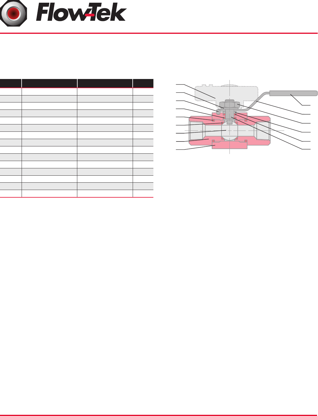
ITEM NAME MATERIAL QTY.
1 Body Stainless Steel 316 1
2 End Connector Stainless Steel 316 2
3 Ball Stainless Steel 316 1
4 Seat* PVDF / PEEK 2
5 Stem Stainless Steel 316 1
6 Body Seal* PTFE 2
12 Thrust Washer* RPTFE / PVDF 1
14 Stem Packing* RPTFE 1
15 Packing Gland Stainless Steel 1
19 Lock Washer Stainless Steel 2
23 Stop Pin Stainless Steel 1
25 Lever Handle Stainless Steel 1
25a Pointer Handle Mazak 3 1
26 Lock Nut Stainless Steel 1
28 Handle Sleeve Vinyl 1
*Items included in repair kit
Dismantling Instruction:
CAUTION- Ball Valves can trap pressurized media when
closed
1. Remove the valve from the pipeline placing the wrench
only on the end connector for each side of the pipe.
2. Clean the valve of any residual media.
3. Remove the retaining pin. Take out each end connector,
holding the body while unscrewing the ends
4. Ensure that the ball is in the closed position and push
the ball and seats out, in either direction.
5. Remove the handle retaining nut and remove the handle.
6. Push the stem out through the body bore to access both
stem seals and remove them.
7. Inspect the ball to ensure no signs of wear or marks,
if it has either, consult factory for a replacement ball.
Visible lines which can not be easily felt are acceptable
on ball surface.
Assembly
1. Ensure that you have the correct repair kit for the
pressure rating of the valve (The repair kit contains the
recommended spares).
2. Ensure that all parts are cleaned prior to assembly.
3. Place the stem seal (5) onto the stem (9), being careful
not to damage it.
4. Insert the stem through the stem hole, pushing firmly
into place. Put the stem packing (10) onto the stem and
fit the packing gland (12) and lever handle (13) in that
order then apply the washer (8) and nut (11) carefully,
so as not to cross thread it. Tighten the handle nut and
ensure that the stem turns smoothly.
5. Place the valve seat (4) into the bore on one side, make
sure the flat face is pointing away from the center of
the valve.
6. Insert the ball ensuring that the slot fits onto drive key
on the bottom of the stem, then turn the handle 90° to
hold the ball in place. Repeat step 5 for second seat.
7. Place the new body seals (5) onto each end connector
and insert into the valve body and with the ball in the
closed position, tighten the end connectors to a torque of
163 ft lb (220 Nm) both sides. Install the retaining pins.
8. Finally adjust the handle nut so as to stop any leaks but
without tightening too tight so as to cause excessive
torque for turning the valve (Normally hand tight plus
1/4 turn.)
19
25a
23
1
2
3
4
6
12
28
25
26
15
14
5
1
Résumé du contenu
Page 1 - SERIES H, HP & HX
Installation and Maintenance ManualSeries H, HP & HX Ball ValvesDate: August 2011 / Page 1 of 1®A Subsidiary of BRAY INTERNATIONAL, Inc.FLOW-TEK,
Produits connexes et manuels pour Équipement Bray HX
 (6 pages)
Équipement Bray S85 Manuel d'utilisateur
 (2 pages)
(2 pages)
 (7 pages)
© 2020, manymanuals.fr. Tous droits réservés | 0.807 s |
 Manymanuals.com
 Manymanuals.de
 Manymanuals.fr
 Manymanuals.it
 Manymanuals.pl
 Manymanuals.cz
 Manymanuals.es
 Manymanuals-pt.com
Commentaires sur ces manuels